
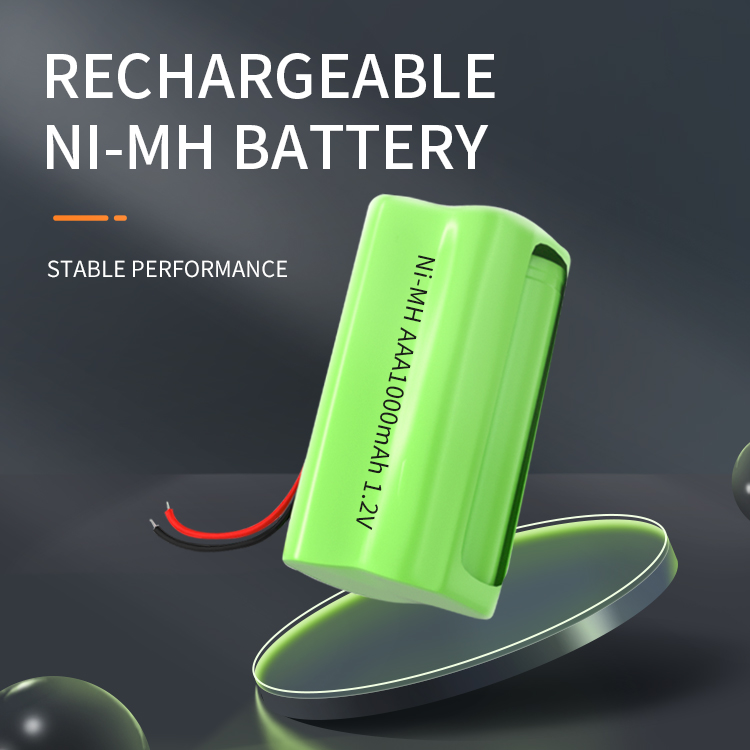
Ni-MH battery management system based on CAN bus
The battery pack is composed of a certain number of single cells connected
in series, which can be charged and discharged hundreds to thousands of times;
in use, attention must be paid to the various characteristics of each single
cell, the battery temperature, the remaining power of the battery and the total
Current and other parameters, because these parameters directly affect the
service life of the battery, it is necessary to optimize the operation and
effective monitoring to prevent the battery from overcharging, over-discharging
and overheating, so as to prolong the service life of the battery and reduce the
cost. battery reliability. The electronics, control, and digital technology that
powers the battery pack can be called digital "battery electronics." Also in the
electronic and digital technology of automobiles, multiple CPUs have been used
to complete the control of various parameters and functions. Considering the
safety of the automobile, the operation must be very reliable, so a parallel
battery pack is developed, which is composed of a certain number of single
batteries Composed in series, it can be charged and discharged hundreds to
thousands of times; in use, it is necessary to pay attention to the various
characteristics of each single battery, the battery temperature, the remaining
power of the battery and the total current and other parameters, because these
parameters directly affect the battery. In order to improve the service life of
the battery, it is necessary to optimize the operation and effective monitoring
to prevent the battery from overcharging, over-discharging and overheating, so
as to prolong the service life of the battery and reduce the cost, especially to
improve the reliability of the battery. The electronics, control, and digital
technology that powers the battery pack can be called digital "battery
electronics." Similarly, in the electronic and digital technology of
automobiles, multiple CPUs have been used to complete the control of various
parameters and functions. Considering the safety of automobiles, the operation
must be very reliable, so the development of parallel
1 Introduction
With the rapid development of high technology and its industry, the battery
pack energy system with large storage capacity has been paid more and more
attention by people, and has been widely used in many fields, such as the new
direction and new hotspot of the development of the automobile industry— —In the
research and industrialization of electric vehicles and hybrid vehicles, it will
be the main supplier of vehicle energy.
The battery pack is composed of a certain number of single cells connected
in series, which can be charged and discharged hundreds to thousands of times;
in use, attention must be paid to the various characteristics of each single
cell, the battery temperature, the remaining power of the battery and the total
Current and other parameters, because these parameters directly affect the
service life of the battery, it is necessary to optimize the operation and
effective monitoring to prevent the battery from overcharging, over-discharging
and overheating, so as to prolong the service life of the battery and reduce the
cost. battery reliability. The electronics, control, and digital technology that
powers the battery pack can be called digital "battery electronics." Similarly,
in the electronic and digital technology of automobiles, multiple CPUs have been
used to control various parameters and functions. Considering the safety of
automobiles, the operation must be very reliable, so a parallel independent
multiple system structure has been developed. Bus connection to form a unified
large system.
2 Management system of distributed structure
2.1 System structure
The system needs to realize different types of multiple functions, and the
centralized or central processing method cannot meet the safety requirements, so
it is natural to adopt a distributed structure; the working environment of the
system is harsh, and it is often under the interference of strong
electromagnetic interference and pulse current. In order to ensure reliable
Considering the adoption and development of high-performance CAN field bus as a
communication system; and CAN bus has been used in automobiles for a long time
and has strong anti-interference performance. At the same time, this technology
is relatively mature and has become the standard for automobile communication.
Therefore, both the internal communication of the system and the external
communication are realized by CAN bus.
This distribution system is designed with CPU80C552 as the common module
platform. Due to the limitation of CPU storage space and calculation, multiple
CPUs must be used to realize various functions required by the management
system. The completed basic system is composed of four modules in parallel: data
acquisition, balanced charging, power estimation and communication display; each
module realizes its function respectively, and communicates data through the CAN
bus, which can realize single battery voltage, total voltage, charge and
discharge current, Acquisition and measurement of temperature, power estimation.
At the same time, the system also has strong scalability, and can carry out
research and development of specific functions such as battery diagnosis and
battery safety performance protection. In the lithium battery management system,
108 batteries use 9 measurement boards, plus 4 basic boards, a total of 13
boards.
Figure 1 The overall structure of the battery management system
2.2 Design of the main module of the management system
The main functions of the system include data acquisition, power estimation
and display diagnosis. Since the 80C552 has the function of 8-way 10-bit A/D
conversion, the acquisition module first uses the linear optocoupler method to
measure the voltage of the single battery, and converts the analog value into a
digital value through its 4 A/D ports and stores it in the memory. The
measurement adopts single-bus technology, and uses Dallas digital chip to
measure the temperature. This chip has 12-bit precision level, which can measure
the temperature of the system very accurately. The total voltage and current
signals are converted into 0-10V signals by special sensors, converted into
digital quantities by 14-bit A/D conversion devices and stored in the
system.
The communication and display module provides dual CAN communication
interfaces, which can transmit data with each module in the system and the
external vehicle system through CAN; at the same time, the system provides RS232
interface, which can realize communication with the PC; the module also provides
a 5-inch half-inch LCD display Drive function, and buttons for man-machine
friendly operation; the module is also equipped with upper and lower limit
alarms and self-test functions for voltage, power, current and temperature to
ensure the safety of the system.
The basic structural block diagram of each system module is shown in Fig. 2
.
Figure 2 Block diagram of module structure
2.3 Electricity Estimation
Electricity estimation uses real-time current integration ampere-hour
method for basic estimation, and then corrects various parameters such as
temperature, self-discharge and aging that affect battery power, and considers
the inconsistency between individual batteries to obtain an accurate battery
pack electricity.
Figure 3 Block diagram of battery power estimation
3 CAN bus system
3.1 Introduction to CAN
CAN bus is a kind of field bus. It is a serial high-speed data
communication bus developed by German Bosch Company in 1986 to solve the data
exchange between many control and test instruments in modern automobiles. It
adopts the physical layer and data link layer in the seven-layer structure of
the ISO/OSI model, and has high reliability, real-time and flexibility.
CAN bus has the following unique advantages:
1) CAN can work in a multi-master mode. Any node on the network can send
information to other nodes on the network at any time, regardless of
master-slave, and the communication method is flexible;
2) CAN can realize point-to-point, point-to-multipoint and global
broadcasting to transmit and receive data. The communication medium adopts
twisted pair, coaxial cable or optical fiber, and the choice is flexible. The
communication distance can reach up to 10km/5kb/s. The rate can reach up to
1Mb/s/40m. The number of nodes on the CAN depends on the bus drive circuit,
which can actually reach 110;
3) When the error is serious, the CAN node has the function of
automatically closing the output, cutting off its connection with the bus, so
that other operations on the bus will not be affected. Adopt NRZ
encoding/decoding method, and use bit stuffing technology. The user interface is
simple, the programming is convenient, and it is easy to form a user system;
4) CAN adopts non-destructive arbitration technology. When two nodes
transmit information to the network at the same time, the node with low priority
stops sending data actively, while the node with high priority can continue to
transmit data without being affected, effectively avoiding the bus conflict.
5) CAN adopts a short frame structure, each frame is 8bit, the transmission
time is short, the probability of interference is low, and each frame
information has CRC check and other error detection measures to ensure that the
data error rate is extremely low.
3.2 CAN bus design
The overall structure of the CAN bus is shown in Figure 4. Two 120Ω
resistors are arranged at both ends of the bus. Their function is to match the
impedance of the bus, which can increase the stability and anti-interference
ability of bus transmission and reduce the error rate in data transmission. The
CAN bus node structure is generally divided into two categories: one uses CAN
adapter card to connect with the PC to realize the communication between the
upper computer and the CAN bus; Data transmission between nodes and CAN bus. In
this system, the CAN controller adopts SJA1000 and 82C200 produced by Philips,
which are used as a sending and receiving buffer to realize the data
transmission between the main controller and the bus; the CAN transceiver adopts
the PCA82C250 chip, which is a CAN controller The interface with the physical
bus can mainly provide the differential transmission capability to the bus and
the differential acceptance capability to the CAN controller.
Figure 4 CAN bus system structure diagram
4 Software design of CAN bus
The three-layer structure model of CAN bus is: physical layer, data link
layer and application layer. Among them, the functions of physical layer and
data link layer are completed by SJA1000. The development of the system is
mainly in the design of application layer software. It mainly consists of three
subroutines: initialization subroutine, sending data and receiving data program.
At the same time, it also includes some data overflow interrupts and frame error
processing.
After power-on hardware reset, SJA1000 must perform software initialization
before data communication can be performed. The initialization process mainly
includes configuring the clock frequency division register CDR, bus timing
registers BTR0 and BTR1, acceptance code register ACR, and acceptance in its
reset mode. The mask register AMR and the output control register OCR etc.
realize the definition of the bus rate, acceptance mask code, output pin drive
mode, bus mode and clock frequency division. The specific process is shown in
Figure 5. The following is the process of SJA1000 sending and receiving data.
The basic process is that the main controller saves the data to the SJA1000
sending buffer, and then sets the sending request TR flag bit of the command
register to start sending; the receiving process is that SJA1000 will receive
from the bus The received data is stored in the receiving buffer, and the host
controller is notified to process the received information through its interrupt
flag bit. After receiving, the buffer is cleared and the next receiving is
waiting. The specific process is shown in Figure 6 and Figure 7.
Figure 5 CAN bus initialization Figure 6 CAN sending data flow Figure 7 CAN
receiving data flow
For example: the format of the total voltage sent by the battery management
system to the vehicle system is listed in Table 1.
Table 1 BCU_VCU_VOLTAGE (0x08) sends back the current voltage of the
battery pack to the VCU
x08) Send back the current voltage of the battery pack to the VCU"
alt="BCU_VCU_VOLTAGE(0x08) send back the current voltage of the battery pack to
the VCU" />
Among them, ID is the address of the receiving node bus, and the voltage
value is multiplied by 10 before sending, and 0x08 indicates that the content of
the sending frame is the voltage of the battery pack.
5 CAN bus application problems
In terms of hardware, a reasonable power supply must be considered, and
attention must be paid to the filtering between the power supply and ground of
each CAN device, as well as the design of the reset circuit; at the same time,
when actually designing the printed circuit board, reasonable wiring,
strengthening the ground wire, and strengthening the system
anti-interference.
In software design, the setting of the CAN bus timer is very critical. BTR0
determines the propagation time period, phase buffer segment 1 and phase buffer
segment 2; BTR1 determines the synchronous jump width and frequency division
value. In the bit timing register, the value set by TSEG1, TSEG2, SJW and BRP is
1 less than its function value, so the setting range is [0.....N-1] instead of
[1..... N]. So the bit time can be obtained by [TSEG1+TSEG2+3]tq or
[synchronization segment+propagation segment+phase buffer segment 1+phase buffer
segment 2]tq, where tq is determined by the system clock tSCL and the baud rate
prescaler value BRP: tq=BRP /tSCL. At the same time, it should also be noted
that since the CAN system clocks of different nodes are provided by different
oscillators, there is a tolerance between the actual CAN system clock frequency
of each node and the actual bit time, and the change of ambient temperature and
the aging of the oscillator affect the initial tolerance , in order to ensure
accurate data transmission, it is necessary to ensure that each node’s CAN
system clock frequency is within a specific frequency tolerance limit.
Therefore, when selecting an oscillator, the node with the highest requirement
for the oscillator tolerance range should be selected as allow. Moreover, in a
scalable bus structure, the maximum node delay and the maximum length of the bus
must be considered. Generally, the delay is 5.5ns/m.
In actual operation, it is often encountered that the CAN bus is blocked or
the bus is suddenly closed. The main reason is that the frame is lost during
data transmission, which causes an error. When the error counter reaches a
certain value, the bus will be automatically closed. Therefore, In the process
of software design, the error state ES bit must be judged in time. When an error
occurs, the software needs to be reset to SJA1000 to restore communication.



















 360° FACTORY VR TOUR
 Whatsapp
 Tel
Tel Email
Email TOP
TOP