- Home
- About Us
- Products
Rechargeable Battery
Lithium Battery 3.7V Lithium Polymer Battery 3.2V LifePo4 Battery 1.2V Ni-MH Battery Button Coin Battery
Battery Packs
3.7V Battery Pack 7.4V Battery Pack 11.1V Battery Pack 14.8V Battery Pack Other Battery Pack
- Subsidiary Company
-
SINO TECHNOLOGY
Know DetailSino Science&Technology Battery Co.,ltd is a high-tech production enterprise which specialize in the R&D and production of Lifepo4 batteries,energy storage battery,portable UPS power supply,personalized customization lithium battery pack etc .


-
SUNBEAM
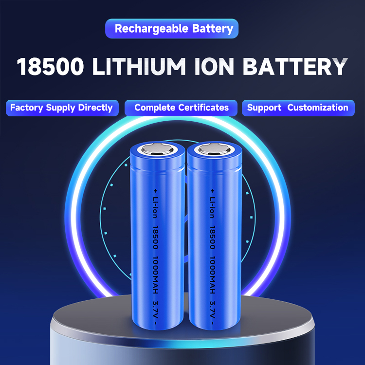
Know DetailEnvironmental cylindrical 18650 21700 32700 26650 14500 18500 lithium ion rechargeable battery, LifePO4 battery,3.7V lithium polymer battery, NiMH battery , NiCD battery ,Lead acid battery,dry cell battery ,alkaline battery ,heavy duty battery, button cell battery etc. we devote to R&D,innovation ,production & sales

-
GREEN POWER
Know DetailShenzhen Green Power Energy Battery Co.,ltd specializes in a wide range of digital battery such as environmental cylindrical 18650 21700 32700 26650 14500 18500 lithium ion rechargeable battery, LifePO4 battery, 3.7V lithium polymer battery, NiMH battery, NiCD battery, dry cell battery, alkaline battery, heavy duty battery, button cell battery etc. we devote to R&D, innovation, production & sales. With automatic production machines we have been exported goods to all over the world over 15years. We have complete exported certificate such as KC, CE, UL, BSCI, ROHS, BIS, SGS, PSE etc

-
DATAPOWER
Know DetailDongguan Datapower New Energy Co.,ltd is a high-tech production enterprise which specialize in the R&D and production&sale of lithium polymer batteries,drone battery,airplane batteries &battery pack etc.

-
SEONG-HEE
Know DetailAnhui Seong-hee New Energy Technology Co.,ltd is a high-tech production enterprise which specialize in the R&D and production of primary batteries. And mainly produces and sells alkaline batteries & carbon zinc batteries. there are size AA, AAA, C, D, 9V etc

-
STD
Know DetailGuizhou STD Battery Co.,ltd is a high-tech production enterprise which specialize in the R&D and production & sale of lithium polymer batteries, drone battery, airplane batteries & battery pack etc.

-
- Honor
- R&D
- News
- Contact Us


 360° FACTORY VR TOUR
 Whatsapp
 Tel
Tel Email
Email TOP
TOP